3.1 Create buffer - LUPMISManual
Main menu:
3.1 Create Buffer
Level of expertise required for this Chapter: Intermediate; general Map Maker training
3.1.1 Buffering
1. If you have a line layer to be buffered, copy it to live layer.
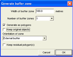
2. Create buffer: In live layer, with roads selected: Selection Manager window: Actions > Polygon manipulation > Generate buffer zones > Generate buffer zone window: Width of buffer zone: Enter width in meters > Number of buffer zones: 1 > Tick ‘Generate as polygons’ > Untick ‘Keep original objects’ > Orientation of zone: External buffer > OK >
3. Buffer creation can sometimes create small polygons at the edge of the buffer polygon. Thus, most, but not all buffers need some postprocessing.
- 3.1 Delete small polygons, which might have been created:
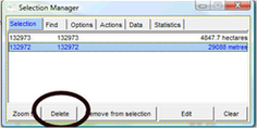
Still in live layer mode: Selection Manager window: Selection: There should be no line (i.e. unit with metres), and no units of very small area (0.0 or 0.1 hectares). If there are, select and delete them.
- 3.2 Remove segments smaller than … m: Still in live layer: Main menu > Edit > Show Selection Manager > Select-tool (at toolbar left) > Select all buffers > Selection Manager window: Actions > Tidying > Remove segments smaller than > Remove segments smaller than window: 10 or 100 (might be upto 500) > OK
- 3.3 If many nodes are displayed, it is recommended that you ‘tidy’ polygon topology: Still in live layer: Right-mouse > Live layer actions > Live layer actions window: Tidying > Tidy polygon topology > OK
If there is any technical problem with the buffering, as described in this Chapter, use the external module Buffer.exe in folder C:\Map Maker (see installation Annex 1.1.1).
3.1.2 Notes on Buffering
The buffer command requires a clean topology. If there is any problem, for example a strange looking result after the buffer operation, you have to clean (‘tidy’) your data, by one or all of these operations:
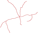
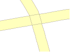
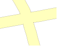
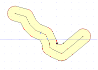
A) The buffer module is not designed to buffer complex line structures, such as an entire road network (displayed below). Such a complex feature has to be broken down into individual ‘legs’ to be buffered, and then joined. (See below for the procedure to join buffers).
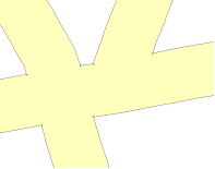
B) Before roads or other line features are buffered, it is recommended to check, if they consist of different ‘legs’ (line segments). You can see this in live layer, if more than one blue label points are shown (see below).

In such a case, you better first remove redundant line junctions (i.e. before you buffer): In live layer > Right-mouse > Live layer actions > Live layer actions window: Tidying > Remove redundant line junctions > OK
C) After the process, if you still have tiny triangular-shaped polygons at the edge of your buffer, you have to eliminate them. Still in live layer mode: Selecting them > right-mouse > Live layer actions > Polygon manipulation > Join adjacent polygons of the same style
For elimination of these tiny polygons, you can also use the Join-tool or Delete-tool from the toolbar left.
D) If all fails, you have to cut the lines into two or more segments with the Cutter-tool from the toolbar left and perform the buffer process individually on each segment.
E) If problems exist and buffering is made around polygons, to convert the polygon(s) to line, and then to buffer from them.
F) Often, roads are defined by many small segments, which are unnecessary and can even harm the process of buffering. It is recommended to remove segments smaller than 10 m for Structure Plans, 100 m for Frameworks (plans):
Still in live layer: Main menu > Edit > Show Selection Manager > Select-tool (at toolbar left) > Select all digitized roads to be buffered > Selection Manager window: Actions > Tidying > Remove segments smaller than > Remove segments smaller than window: 10 or 100 (might be upto 500) > OK
G) If you like to create a buffer only on one side only of a line (e.g. only one side of the road, or only inland of the coast), additionally to have to cut one side away:
Extend on each end the central line (e.g. road or coastline) beyond the buffer area, and save this into a temporary file.
Reload the buffer and bring it into the live layer > right-mouse > Live layer actions > Live layer actions window: Basic operation > Cut with file > OK > Cutter file > Select the line, which divides the left side from the right side. The buffer area should then be split into two units. Select one and delete it.
Alternatively, at the stage of digitizing you have the option to buffer only one side of the line (see Chapter 3.1.4 below).
3.1.3 Joining Of Buffers In Complex Road Networks
If you have a junction of two roads, which you want to merge into one buffer, you first create two buffers independently, copy them both to the live layer, and merge them by:
1. Use the Cutter–tool from the toolbar left to cut from (1) to (2) and from (3) to (4). In both cases, cut as close as possible to the boundary of the other buffer polygon.
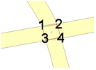
2. Delete the overlapping, cut part: Select the central part (most likely, you will then have also the two buffers selected, i.e. you have to de-select them by shift + select the one buffer polygon), then the same with the other buffer polygon. You can then delete.
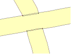
It should look like this:
3. Use the Snap-tool from the toolbar left to fix the close boundaries together (start with snap on one side of the double boundary, and click again on the other side) and repeat for the other side. It should look like this:

4. With the Join-tool from the toolbar left (moving from one side of the boundary to the other) combine the two polygons, and again on the other side:
Another example of joining buffers, here of a T-junction:

Both buffers have to be created independently and to be now both in live layer.
1. With the cutter you cut the end of buffer polygon A close to the border of polygon B (1).

2. Select the cut-off part only, and delete it. (To select it, you might have to select it, and then de-select buffers A and B by holding the shift-key and selecting A, then B)
3. Snap the boundaries to make it one boundary (2)
4. Join the two buffer polygons A and B
3.1.4 Buffering During The Process Of Digitizing
Digitize a line, as explained in Chapter 2.2. Finish the line with right-mouse > Line window: Actions > Create buffer zone > OK > Buffer zone window: Specify width of buffer zone (in meters) > Number of buffer zones: Normally, 1 > Tick ‘Generate as polygons’ > Orientation of zone: Normally, Buffer on both sides > OK

The buffer will be created on both sides of the line:
3.1.5 Cleaning of Buffers
Created buffers have an irregular pattern of vertex points. It might happen, that there is a very high density of small red vertex points at the buffer bends.

It is recommended to remove the many vertex points shown as small red points at the bends of the buffer units.
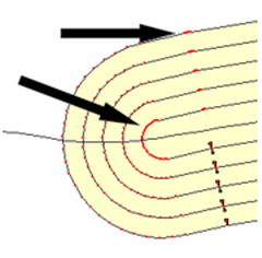
Main menu > Edit > Show Selection Manager > Selection Manager window: Find > Find all > Find > Actions > Tidying > Remove segments smaller than > Remove segments smaller than window: 50 m > OK
3.1.6 Buffering for Plan Preparation
See also Chapters 7.4.3, 7.5.3 and 7.6.3 for actual work on buffering for plan preparation.
- - - - -
More reading:
'GIS Introduction for LUPMIS: Vector Analysis (Chapter 9)'.