5.3.3 Georeference scanned map - LUPMISManual
Main menu:
5.3.3 Georeference Scanned Map
Level of expertise required for this Chapter: Advanced; general Map Maker training
You should have a scanned map with at least two points (‘ground control points’), of which you know the UTM coordinates. (With three or more points, the process is slightly different and more complex, but will yield better results; see Note 4 below).
There are various ways to define the coordinates of ground control points:
A) The best way is to have the GPS readings (in UTM) collected during field trip.
B) If no GPS reading is available, coordinates of the points can be taken from well-referenced aerial photo (or satellite image).
C) If both are unavailable, approximation can be done with existing features of another map layer.
D) A very rough approximation can be done with coordinates shown on the hardcopy maps. Prior to the georeferencing, it has to be investigated, which coordinate system is used at the hardcopy map (some advice in Annex 8). Coordinates can be in lat / long, in UTM, in War Office or another system; units can be in meters or feet.
- - - - -
There are six steps for the entire process:
Define, fix and assess two (or more) ground control points (GCP)
Convert image to correct format
Clip (i.e. remove outside marginalia)
If contract is not strong enough, you might have to enhance the contrast
Calibrate image
Check
1. Define, fix and calculate two (or more) control points
- - - - -
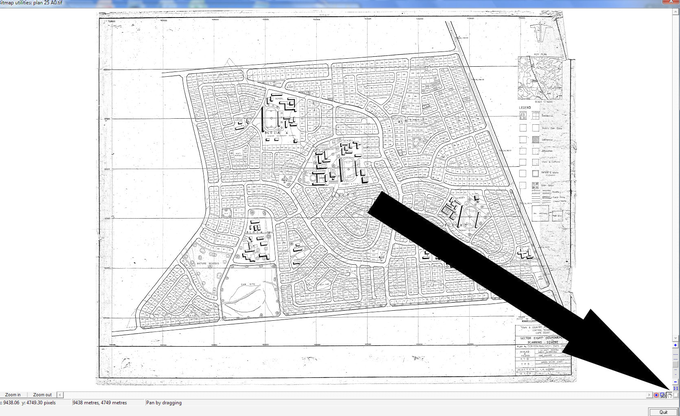
2. Clip any outside information away (frame, legend, scale or any other ‘marginalia’). Follow exactly the map frame.
You best do this in Paint Shop Pro: Select the actual frame with the Select-tool (from the toolbar left) and then Main menu > Image > Crop to Selection.
- - - - -
3. You might have to enhance the contrast of the map.
You best do this in Paint Shop Pro: Adjust > Brightness and Contrast > Brightness / Contrast > Brightness/Contrast window: Increase the contrast value and brightness value, if necessary > OK
- - - - -
4. Convert image to correct format
If the image is at a high resolution (i.e. more than 3000 pixels at x or y direction), it is recommended to ‘resize’ the image to a smaller size, for example 2000-3000 in one direction.
In Map Maker: Main menu > Utilities > Bitmap utilities > Reduce size > Select folder and file > Write to a new file > Select format (e.g. TIF) > Specify new file name > Save > OK > Enter multiplication factor: 0.5 will reduce it to half > OK
See part B of Chapter 5.3.1 and part C of Chapter 5.3.2 for similar descriptions.
Alternatively, you can do this also in Paint Shop Pro: Main menu > Image > Resize > Resize window: Pixel dimensions: New: 2500 OK
The source image can be in JPG or TIF file type (JPG does not always-always work!).
If your image file is not in JPG or TIF format, you have to convert it:
In Map Maker: Main menu > Utilities > Bitmap utilities > Convert file format > From ... > Select folder and file > Select format: TIF > Specify new file name > Save > Map Maker Calibration > OK
Or, you can do this in Paint Shop Pro: File > Save As… > Save As window: Select folder > Save as type: TIF > Specify file name > Save
Note 1: TIF files are considerably larger, and not preferred to JPG files at many applications. But for this purpose they are the preferred option.
- - - - -
5. In Map Maker: Main menu > Utilities > Bitmap utilities > Calibrate scan > Two known points (if you have more than 2 points, see below) >
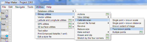
> Select file type TIF > Select folder and filename > > Bitmap utility window: Zoom out (with the button bottom right) >
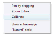
For the first point of known coordinates, you might have to zoom in: Right-mouse > Zoom to box, and define the box
Select the point: Right-mouse > Calibrate, and move round cursor precisely to location, click >
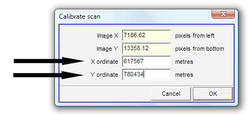
> Enter x coordinates (UTM, number between 200,000 and 1,000,000) >
> Enter y coordinates (UTM, number between 500,000 and 1,300,000) >
Repeat procedure above for the second point.
> Transform file window: Write to new file > Save As window: Select folder > Enter filename > OK
The processing might take long time...
> Choose calibration technique window: As part of the file (MM calibration) > OK. (For explanation of the calibration, see Annex 2.3 about 'world files').
This process will also take some time. There will be no message, that it has finished.
- - - - -
6. Check
Display the calibrated image with an overlay of any other available map layer and in particular with good tracked GPS data (for example, roads).
Most sector layout maps have a grid. This is either in feet (1000 feet = 305 m) or in meter (200 m). Check the distance between the grid lines with the Tape-tool from the toolbar left.
Note 2: If no image is shown at all, the input file might have distorted layer(s). To fix, save it as a JPG file, load this JPG file, and save it as a TIF file again, as recommended in the first Chapters of these instruction, which can all be done in your graphics program.
- - - - -
Note 3: Convert TIF format to more handy, faster JPG format: Main menu > Utilities > Bitmap utilities > Convert file format > from TIF > Choose file window: Select folder and file > Save As window: Select file type: jpg > Define file name > Save > Select calibration option window: Map Maker calibration > OK
- - - - -
Note 4: If you calibrate with more than two points, the result might have a better ground accuracy:
Select the menu option ‘Multiple points’, define the points on the map in a similar way as described above, but then enter the UTM coordinates at the listing on top of the screen under World-x and World-y. After all ground control points are entered, press OK at the bottom to start the process.
- - - - -
Note 5: The procedure of entering more than two ground control points (see Note 4 above) allows you to quality-control the georeference, as it shows the RMS error (root mean square indicating the deviation of distance of the points from an ideal location) next to the point and the all-over error.